Marantz AV
Surround Receiver SR-18 U,K,KS
Rated
Power
Stereo Mode FRONT (20 Hz − 20 kHz) ..... 8 ohms 140W / Ch (2ch driven)
Center (40 Hz − 20 kHz) ............................ 8 ohms 140W / Ch
Surround .................................................... 8 ohms 140W / Ch
Power
Requirement ........................ AC 120V 60 Hz (U version)Stereo Mode FRONT (20 Hz − 20 kHz) ..... 8 ohms 140W / Ch (2ch driven)
Center (40 Hz − 20 kHz) ............................ 8 ohms 140W / Ch
Surround .................................................... 8 ohms 140W / Ch
AC 220 50/60 Hz (K version)
AC 230V 50 Hz (KS version)
Power Consumption ............470W
Dimension ( MAX )
Width ...................................18 inches (458 mm)
Height ..................................7-½ inches (190 mm)
Depth ...................................19-½ inches (496 mm)
Weight .................................49.7 lbs. (22.5 kg)

FACTORY
mode (Tracking point memory)
This FACTORY mode can be use for measurement of the tuner circuit.
When the product is POWER ON, press both [ MEMO ] and [ DISPLAY OFF ] buttons simultaneously for more than 3 seconds.
FLD shows "FACTORY" for 3 seconds. Press [ PRESET ] button, FLD shows "PRESET SEL".
This FACTORY mode can be use for measurement of the tuner circuit.
When the product is POWER ON, press both [ MEMO ] and [ DISPLAY OFF ] buttons simultaneously for more than 3 seconds.
FLD shows "FACTORY" for 3 seconds. Press [ PRESET ] button, FLD shows "PRESET SEL".
FLD segment check mode
This mode is available to check all luminous segments by the following steps.
1. When the product is FACTORY mode ( Refer to above mentioned "1. FACTORY mode"), press [ DISPLAY OFF ] button. FLD shows "SERVICE" for 2 seconds.
2. All segments and all LED light up for 5 seconds.
3. Each segment lights up step by step.
4. Press [ DISPLAY OFF ] button again, then this mode will be stopped and the product will be FACTORY mode.
Version of microprocessor (CPU)
This program is available to confirm the version of each CPU by the following steps.
QY01 (main) : When the product is POWER ON, press both [ CL ] and [ TREBLE ▼ ] buttons simultaneously over 3 seconds.
FLD shows the version of program code for QY01.
Q691 (DSP) : When the product is POWER ON, press both [ CL ] and [ BASS ▼ ] buttons simultaneously over 3 seconds.
FLD shows the version of program code for Q691.
Input and output test mode
This mode is available for the functions as shown in Fig 1 by the following steps.
1. When the product is FACTORY mode ( Refer to above mentioned "1. FACTORY mode"), press both [ MEMO ] and [ TREBLE▼] buttons simultaneously.
2. FLD shows "AUTO D1". By pressing both [ MEMO ] and [ TREBLE ▼ ] buttons simultaneously each time, the mode is changed.
Input selection mode (without setting to system setup menu)
This mode is available to select the input without setting to system setup menu by the following steps.
1. When FLD shows “AUTO D1” (4. Input and output test mode"), the input can be shifted by pressing [ MODE ] button for the remote commander only each time.
5.1 channels output mode
This mode is available to output the same signal from 5 channels, even though 2 channels audio signal comes in.
As the result, all channels output can be confirmed by using analog stereo signal or PCM audio signal.
AC-3 or DTS source is not necessary to output from any channel in this mode.
1. When FLD shows “ALL CH D1” (Refer to "4. Input and output test mode"), the input can be shifted by pressing [ MODE ] button of the remote commander.
2. Supply to 2 channels PCM signal for digital input or 2 channels analog signal for analog input. But, Left channel and Right channel of input signal should be equal.
3. Then each output from the product is the same as the input signal. (Sub-woofer channel is respond to lower than 80Hz signal)
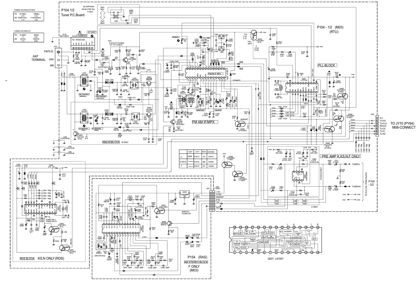
Circuit Diagram (Full)

Click on the Schematics to zoom in


Exploded view

Transistor
MUTE mode
In mute situation on the product, output signal is muted by Volume control IC and muting transistor.
But, this mode is available to work the muting transistor only by the following steps.
1. When the product is FACTORY mode ( Refer to "1. FACTORY mode"), press [ MUTE ] button for remote commander only.
2. FLD shows “TrMUTE ON”, then muting transistor circuit is active only.
How to reset the product
When the product is POWER ON, press both [ CL ] and [ DISPLAY OFF ] buttons simultaneously.
FLD shows "DEFAULT" for 3 seconds, and then all memories are cleared.
Thermostat
circuit confirmation
1) When the product is POWER ON, remove the wire W701 from the connector J715 (P704).
2) FLD shows "ERROR PWR1".
3) Confirm the product is POWER OFF after 3 seconds.
4) Connect the wire W701 to the connector J715 (on P704).
5) Confirm the product is standby status.
1) When the product is POWER ON, remove the wire W701 from the connector J715 (P704).
2) FLD shows "ERROR PWR1".
3) Confirm the product is POWER OFF after 3 seconds.
4) Connect the wire W701 to the connector J715 (on P704).
5) Confirm the product is standby status.
Cooling
fan confirmation
Fan failure sensor confirmation
1) Set to be SPK output 1W from the front channel.
2) Connect the 1pin (LOCK) of the connecter JN10 (on P754) to chassis (GND level) by a wire.
3) After 6 seconds the SPK relay works, and the SPK output isn’t output.
Temperature sensor confirmation
1) Connect a resistor (470ohms 1W) between JN10 3pin (T-2CH) and DC +12Voltages.
2) Confirm the cooling fan starts working. (Status : JN09 between 1pin and 2pin = +7.5 volt, Fan speed = Low)
3) Remove the resistor.
4) Confirm the cooling fan stops.
5) Connect the resistor between JN10 4pin (T-3CH) and DC +12Voltage.
6) Confirm the cooling fan starts working again.
7) Remove the resistor.
8) Confirm the cooling fan stops.
9) Connect the resistor between JN10 3pin (T-2CH) and DC +12 Volt. And then connect another resistor between JN10
4pin (T-3CH) and DC +12 Volt.
10) Confirm the cooling fan starts working.
11) And then connect the resistor between JN10 2pin (SPEED) and DC +12 Volt.
12) Confirm the cooling fan changes to work with high speed. (Status : JN09 between 1pin and 2pin = +11.5 Volt, Fan speed = High)
Fan catching a foreign body sensor confirmation
1) Connect the resistor (470ohms 1W) between JN10 3pin (T-3CH) and DC +12 Volt.
2) Confirm the cooling fan starts working. (Status : JN09 between 1pin and 2pin=+7.5 Volt, Fan speed = Low)
3) Set to be SPK output 1W from the front channel.
4) Hold the cooling fan by hand and stop it.
Notes: Take care of wound in the hand.
5) After 6 seconds the SPK relay works and the SPK output isn’t output.